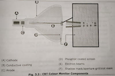
A CRT color monitor contains millions of tiny red, green, and blue phosphor dots that glow when struck by an electron beam that travels across the screen to create a visible image. The illustration below shows how this works inside a CRT.
- The terms anode and cathode are used in electronics as synonyms for positive and negative terminals. In a cathode ray tube, the "cathode" is a heated filament. The heated filament is in a vacuum created inside a glass "tube."
- The ray" is a stream of electrons generated by an electron gun that naturally pour or a heated cathode into the vacuum. Electrons are negative.
- The anode is positive, so it attracts the electrons pouring off the cathode.
- This screen is coated with phosphor, an organic material that glows when struck by the electron beam.
- There are three ways to filter the electron beam in order to obtain the correct Image on the monitor screen: shadow mask, aperture grill and slot mask.
- These technologies also impact the sharpness of the monitor's display.
CRT Features and Attributes
Shadow-mask
- A shadow mask is a thin metal screen filled with very small holes.
- Three electron beams pass through the holes to focus on a single point on a CRT displays' phosphor surface.
- The shadow mask helps to control the electron beams so that the beams strike the correct phosphor at just the right intensity to create the desired colors and image on the display.
- The unwanted beams are blocked or "shadowed."
Aperture-grill
- Monitors based on the Trinitron technology, which was pioneered by Sony, use an aperture-grill instead of a shadow-mask type of tube.
- The aperture grill consists of tiny vertical wires.
- Electron beams pass through the aperture grill to illuminate the phosphor on the faceplate.
- Most aperture-grill monitors have a flat faceplate and tend to represent a less distorted image over the entire surface of the display than the curved faceplate of a shadow-mask CRT.
- However, aperture-grill displays are normally more expensive.
Slot-mask
- A less-common type of CRT display, a slot-mask tube uses a combination of the shadow-mask and aperture-grill technologies.
- Rather than the round perforations found in shadow-mask CRT displays, a slot-mask display uses vertically aligned slots.
- The design creates more brightness through increased electron transmission combined with the arrangement of the phosphor dots.
Block Diagram and Functions of Color Monitor
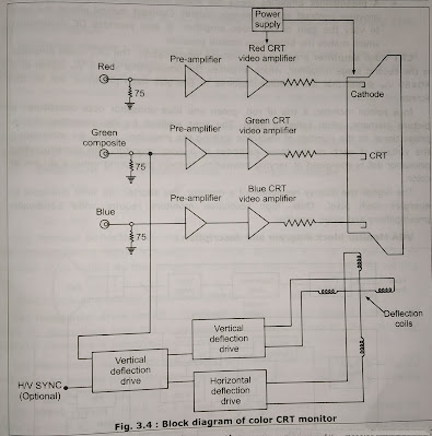
Fig. 3.4 Shows block diagram of a color CRT monitor. It has three main functional blocks:
- Power supply.
- Video signal processing and amplification.
- Horizontal/vertical deflection and synchronization.
- As shown in Fig. 3.4, the video signal from the host computer to the monitor is carried via transmission line or a coaxial cable.
- This video signal, which is usually a 1 vpp (voltage peak to peak), is amplified before the signal is applied to the CRT's cathode.
- The amplification of the video signal is done in two stages.
- A preamplifier amplifies the 1 Vpp video signal to a 4+-6 Vpp signal. It provides contrast and brightness control. Contrast control allows the user to vary the gain of the video amplifier. It also provides DC restoration which makes the brightness control possible.
CRT video amplifier provides high voltage amplification. The CRT video amplifier is the second stage amplifier, which amplifies the preamplifier's 4+6 Vpp signal to a 40–60 Vpp signal that the cathode requires to energize each phosphor dot on the screen.
In a color monitor, a trio of red, green and blue phosphor dots constitutes a picture element, often called a pixel. The light emitted by the phosphor dot is proportional to the number of electrons striking the phosphor. Thus, by modulating the voltage of each of the three cathodes in a color monitor, the corresponding phosphor dot is energized at varying intensities, thereby producing various shades of color.
The higher the display resolution of a monitor, the shorter the time available to energize each pixel. Thus, high resolution monitors require wide bandwidth preamplifiers and video amplifier.
VGA Monitor block diagram and description :
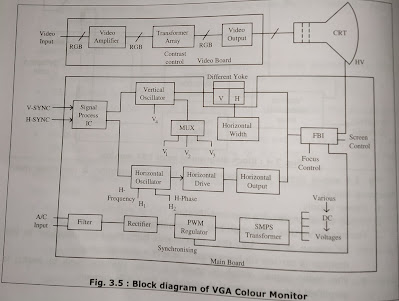
The Fig. 3.5 above shows the schematic of standard VGA color monitor. The working of various functional blocks is as described below :
VGA color monitor uses R, G, B analog input signals and separate (TTL) synchronous signals.
(a) Power circuits : The power supply circuit is a synchronizing type switching power circuit and substantially consist of Line Filter IC, Rectifier, Pulse Width Modulator (PWM) Regulator IC and SMPS converting transformer.
The synchronization is done by the pulse induced at the core of EHT or flyback transformer (FBT).
(b) Mode Detecting circuit : This monitor has 3 different resolution modes depending on the polarity of synchronous signals. Mode detecting circuits is composed of signals processing IC, Multiplexer (MUX) IC etc.
(c)Vertical deflection circuit : This consist of MUX, Vertical Oscillator IC etc. The V-synchronous signal is applied to vertical oscillator IC. The Permanency of oscillator is controlled by the voltage on specific of this IC. This is done by varying V4.
Thus, it acts as a voltage controlled oscillator.
(d) Horizontal drive circuit : The H-synchronous signal is applied to Horizontal Drive IC. The output from FBT is connected to Horizontal Drive IC. The Horizontal oscillator frequency is controlled by Hi and Horizontal phase is controlled by H2.
(e) Horizontal output circuit : This generates the horizontal scan of high voltage to be applied to picture tube. The function of the H-output stage is to serve as switch for the H-output circuit.
(f) Video circuit : The R, G, B analog signals are applied to transistor away via video amplifier IC. These signals are provided to cathode of CRT. The RGB output gains are controlled by variable 'R' inside.


_11zon.jpg)


.png)

_11zon.jpg)
